
Contactor wiring: start-stop latching and forward-reverse motor control
Updated: 2026-10-26
For 230/400 V installations to IEC standards (Europe, UK and most of the world). North America uses different voltages, colours and rules: see the “Around the world” notes.
Contactor markings (EN 50005 / IEC 60947)
| Terminals | What it is |
|---|---|
| A1-A2 | the coil (for example 230 V AC: line to A1, neutral to A2) |
| 1-2, 3-4, 5-6 (L1-T1, L2-T2, L3-T3) | main contacts: odd from the supply, even to the motor |
| 13-14 | auxiliary contact NO (normally open): for example the hold-in |
| 21-22 | auxiliary contact NC (normally closed): for example the interlock |
On auxiliary contacts the second digit gives the type: 1-2 = NC, 3-4 = NO. Always check the print on the actual device.
Start-stop with latching
The basic control circuit: a START button (NO) energises the coil, and the contactor's own 13-14 contact, wired in parallel with START, holds the coil in after you release the button. A STOP button (NC) in series with the coil breaks the circuit and the motor stops.
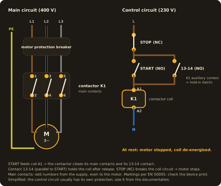
A nice side effect: after a power cut the motor does not restart on its own, because the latch drops out. That is a safety feature.
What else sits in the coil circuit
Any device whose contact is in series with the coil can stop or start the motor:
- a thermostat, switching a fan or heater when the temperature leaves its setting,
- a phase failure and phase sequence relay, which opens its contact if a phase is lost or the order is wrong, stopping the motor before it is damaged.
Forward-reverse (reversing) control
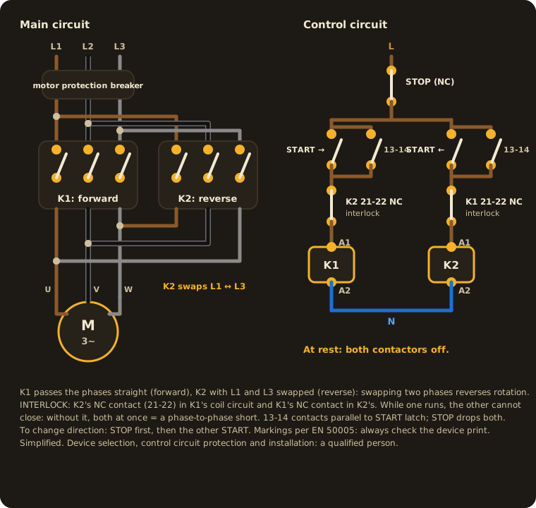
A three-phase motor reverses when you swap any two phases (for example L1 with L3). Two contactors do it:
- K1: phases straight → forward,
- K2: two phases swapped → reverse.
The interlock is mandatory: K1's NC contact goes into K2's coil circuit and K2's NC contact into K1's. While one is on, the other physically cannot close. Without it, both closing at once means a phase-to-phase short circuit. Reversing contactor sets often add a mechanical interlock as well.
A single-phase motor behaves differently: swapping L and N changes nothing. See reversing a single-phase motor.
The motor protection breaker
In front of the contactor there is usually a motor protection circuit breaker with two trips:
- thermal: for sustained overload (jammed shaft, lost phase),
- magnetic: instant trip on a short circuit.
Set it to the rated current on the motor's rating plate. Bigger motors are started more gently: star-delta starting.
Did this answer help?